Rutherford Backscattering Spectrometry (RBS) Tutorial
Home » Rutherford Backscattering Spectrometry (RBS) Tutorial
In this RBS tutorial from EAG Laboratories, we present the history of Rutherford Backscattering Spectrometry, as well as the scientific principles behind the instrumentation, theory, and data provided by this analytical technique.
Rutherford Backscattering (RBS) is based on collisions between atomic nuclei and derives its name from Lord Ernest Rutherford, who in 1911 was the first to present the concept of atoms having nuclei.
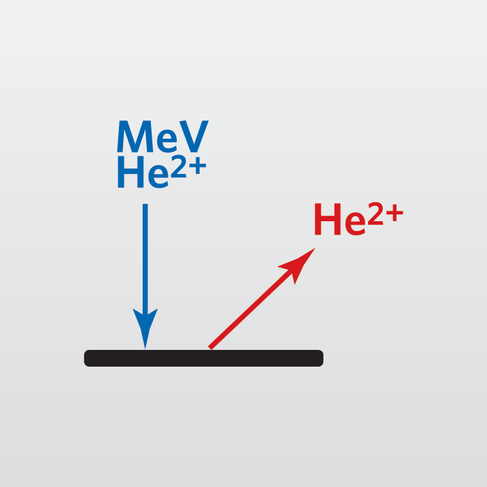
It involves measuring the number and energy of ions in a beam which backscatter after colliding with atoms in the near-surface region of a sample at which the beam has been targeted.
With this information, it is possible to determine atomic mass and elemental concentrations versus depth below the surface. RBS is ideally suited for determining the concentration of trace elements heavier than the major constituents of the substrate. Its sensitivity for light masses, and for the makeup of samples well below the surface, is poor.
History
By 1909, Ernest Rutherford had established that alpha particles consisted of helium with +2 charge. The backscattering experiment that bears Rutherford’s name was suggested by Hans Geiger (of Geiger counter fame). However, it remained for twenty-year old undergraduate Ernest Marsden to actually do the first measurements.
Marsden observed that the vast majority of alpha particles (He++) passed cleanly through a thin gold foil, but that some were scattered at all angles from the incoming He++ beam. Rutherford proceeded from this observation to propose the existence of the atomic nucleus. The key feature of Rutherford’s nucleus proposal is that a very small volume contains most of the atomic mass. The alpha particles scatter from nuclei as a horde of billiard balls would scatter if propelled at a bowling ball.
Rutherford backscattering spectrometry (RBS) is the measurement of energies of these backscattered particles. These energies depend on the identity of the atom from which the alpha particle scatters, the angle of scatter, and the depth into the sample to which the particle travels before scattering. Thus, RBS can be used for elemental analysis, especially of surfaces.
One early use of RBS (called the alpha-scattering experiment at the time) was elemental analysis of lunar soils as part of the Surveyor V scientific payload in 1967. Most early RBS experiments used radioactive sources of alpha particles. Today, the intense pencil like beam of alpha particles required to produce a modest backscattered signal is most commonly provided by a charged particle accelerator.
Instruments
The three main components of an RBS instrument are a source of helium ions, an accelerator to convert them to high energy alpha particles, and a detector to measure the energies of the backscattered ions. The type of accelerator determines the configuration of the other components. Single-ended accelerators have the ion source floating at high voltage. Electrical isolation of the megavolt potentials is achieved by housing the terminal in a tank filled with an insulating gas, usually SF6. One disadvantage of locating the ion source within the tank is that it is difficult to change or replenish the source.
The tandem accelerator is a clever innovation. The tandem accelerator uses a positive terminal located in the center of the device. Negatively charged particles are injected into the accelerator and attracted to the terminal where a stripper element removes two or more electrons from each particle. The positive terminal repels the resulting positive ion back toward ground. Thus the particle acquires energy both before and after the terminal.
The tandem configuration has two important advantages over a single-stage setup. First, lower terminal voltages are required, and second, both the source and the ion exit operate near ground potential. The main disadvantage is that inefficiencies of He- production and charge stripping lower He++ beam current to about 100 nA for a tandem versus 1 mA for a single-ended accelerator. Fortunately, most RBS experiments can only use about 100 nA because of detector limitations. A typical RBS installation uses a tandem accelerator, producing a 2.25 MeV He++ beam by removing three electrons from He- at the + 750 KV terminal.
Tandem Accelerators
There are four main components of a tandem accelerator:
- A charged particle beam line in a tank containing high voltage components and an insulating gas.
- An electrode called the terminal supplied by a high voltage source.
- An electron charge stripper located at the terminal.
- A vacuum system for the charge stripper and beam line.
Although large accelerators can often fill entire halls, smaller accelerators are suitable for RBS. Such accelerators require investments in the $300,000 range, and suitable end stations for analysis and control cost an additional $50,000 to $200,000. While these are certainly expensive devices, they are not out of line with other analytical instruments.
Voltage Sources
The oldest form of accelerator is the Van de Graaff, named for Robert Van de Graaff, who put a suggestion by Lord Kelvin into practice. Its distinguishing feature is charge transfer on a moving belt with one pulley at ground and the other at the terminal.
Charge is placed on the belt by a comb of corona points. A second set of points removes the charge at the terminal. Although the traditional Van de Graaff accelerator is single-ended, the voltage source can be used in a tandem machine.
A well-known variation is the Pelletron which is identical to a Van de Graaff, except that a chain with alternate links (pellets) of metal and insulator replaces the belt. This chain provides more uniform charge transport than the belt, resulting in more stable voltage.
A Tandetron accelerator uses a voltage doubler power supply fed by a radio frequency signal. There are no moving parts, reducing the need for expensive maintenance. The voltage from the Tandetron device is also very stable. Terminal voltage stability influences spectroscopic resolution.
Beam Line and Tank
Electrical isolation of the accelerator terminal obviously requires good insulators. Because air ionizes and becomes conducting in high electric fields, the accelerator components must be arranged to minimize electric fields. Thus, one guiding principle of accelerator design is elimination of any sharp points or edges that produce high electric fields. The high voltage components are housed in a pressure vessel filled with sulfur hexafluoride gas (SF6) because this gas resists electrical breakdown better than air.
The terminal and the beam line require mechanical support, a more demanding task because of the forces exerted by the pulley used as one end of a Van de Graaff or Pelletron voltage source. The beam line consists of alternating insulator and conductor sections connected to the terminal voltage along a resistor chain to linearize the electrical potentials and reduce electric fields between components. The beam line and the terminal are surrounded by a series of smooth conducting rings also connected along a resistor chain to the terminal voltage. These precautions serve to reduce voltage gradients between accelerator components and thus minimize electric fields. The precautions are necessary because the 750 kV terminal has the potential to produce very large sparks.
Stripper Elements
The He- ions have substantial kinetic energy (typically 750 keV) when they arrive at the positive terminal. High energy ions lose electrons in grazing collisions as they travel through any material. The ions also give up a small amount of kinetic energy for each lost electron. However, the lost energy is small compared to the kinetic energy of the negative ions as they pass the terminal.
Convenient electron stripper materials (located at the terminal) include thin foils and gases. A foil is easier to use since it simply hangs in the beam path. However, the thickness of the foil can increase by carbon deposition (from residual carbon containing gases in the vacuum system) or decrease by sputtering. Foil thickness affects stripper efficiency and beam energy. The foils must occasionally be replaced, which involves opening the tank and the beam line.
Because gas cells operate more predictably and avoid maintenance problems, they have become more common. Gas cells consist of concentric tubes, perhaps 0.3 m long. The ends are closed except for small holes through which the ion beam passes.
The outer tube is connected to an extra vacuum pump and gas is leaked from an external source into the inner tube to produce a pressure of 1 to 10 millitorr. This differential pumping in the outer tube reduces the amount of gas leaking into the beam line.
Because of the pressures required to maintain a gas cell, pressures in the flight tube (measured at the end of the accelerator) rise into the 1 to 10 microtorr range. Lower pressures are possible with a stripper foil. However, the modest collisional cross section of high energy ions with gas molecules diminishes the requirement for high vacuum in RBS experiments.
Source of Negative Helium Ions
The He+ or He++ ions required for a single ended accelerator come from plasma ion sources. The duoplasmatron starts with a low voltage arc burning between cathode and anode. The helium plasma is geometrically and magnetically confined, and ions are extracted by a strong electric field.
The radio frequency plasma source also generates He+ ions. Radio frequency sources are more common in single-ended accelerators, because they produce He++ more efficiently than duoplasmatrons. A typical source produces 1 mA of He+.
Tandem accelerators require negative helium ions. Helium is the most inert of the inert gases; it tends not to gain or lose electrons. The ion source must overcome this natural tendency of helium not to form negative ions. The source operates in two stages. First, positive ions are produced as described above. An alkali metal channel converts He+ into He- in a second stage.
This charge exchange happens as He+ passes through hot alkali metal vapor. Rubidium is used in the illustration, but all of the alkali metals have sufficient reducing power to form He-. The charge exchange process is inefficient; 1 milliamp of He+ leads to 1 microamp of He-. The negative ions are extracted from the alkali metal channel and injected into the tandem accelerator at 20 to 30 keV.
Focusing Elements
Two ion optical components are usually placed between the accelerator and the sample chamber. A magnetic field separates any He-, He, or He+ from the He++ beam. A quadrupole lens shapes the beam and focuses it into the sample chamber. Relatively strong ion bending and focusing components are required for these high energy (rigid) beams. The high energy beam provides an important analytical advantage.
Samples in RBS can be insulating, in contrast to most charged particle analytical methods. Even if such samples charge to a few kilovolts, the rigid beam is barely deflected. Sample charging causes only slight perturbations in RBS spectra because the kilovolt charging effect is a small fraction of the megavolt particle energies.
Sample Chamber
The main sample chamber components are a stage, one or more detectors,a beam entrance, and the vacuum system. The chamber can be as simple asa flange with a sample and a single energy dispersive spectrometer attached.
More typically, the samples mount on a five-axis goniometer, which isconvenient for loading many samples into the vacuum system and analyzingthem sequentially. The goniometer can also tilt and rotate the samples.Comparing spectra obtained at different incident and exit beam angles providesbetter characterization of sample composition as a function of depth. Randomlytilting and rotating a sample relative to the incident beam avoids variationsin the spectrum that arise because the incident beam travels down a channelin the sample’s crystal structure. Two surface barrier detectors (one normal angle, one grazing exit), are included in a typical RBS sample chamber.
Spectroscopy
Alpha particles come from the accelerator and strike the sample surface. Energies must be measured for those few particles that recoil back into the detector. Surface barrier silicon detectors are used in RBS. Since these devices are essentially diodes, they are often called semiconductor diode detectors. The high energy charged particles produce electron-hole pairs in the semiconducting material. The detector is operated with an electrical potential (typically 4 kV) between the front and back surfaces. In the resulting electric field, the electron-hole pairs produce a current proportional to the energy of the charged particle.
The average energy expended by He++ to produce one electron-hole pair is approximately 3.7 eV. This is sometimes called the ionization energy of the detector. Each 1 MeV particle produces about 2700 electron-hole pairs. The fluctuation or variance in the number of charge carriers affects the spectroscopic resolution. The theoretical minimum variance (which follows Poisson statistics) is equal to the number of charge carriers. The standard deviation equals the square root of the variance. The Fano factor is the ratio of the observed to this theoretical minimum variance. The Fano factor implicates other sources of peak broadening, typically incomplete charge collection and variations in dead layer loss.
Incomplete charge collection is minimized by high purity semiconductors which provide relatively few sites for electron-hole pair recombination. The energy lost before the charged particle reaches the active volume of the detector (dead layer loss) is minimal because this layer is thin (about 100 nanometer) in surface barrier detectors. Since this thickness corresponds to only about 0.4% energy loss for 1 MeV He++, small variations in the energy loss are insignificant for typical RBS experiments. High quality silicon surface barrier detectors are thus nearly ideal for alpha particle spectroscopy.
Particle arrival times at the detector are randomly spaced in time, leading to the possibility of interference between measurements when particles arrive at nearly the same time. This phenomenon, called pulse pile-up, becomes a serious problem at high particle arrival rates. There are two types of pile-up. Tail pile-up involves the superposition of pulses on the long duration tail or undershoot from a preceding pulse, leading to reduced spectral resolution. High quality electronic circuits minimize tail pile-up. Two pulses sufficiently close together to be treated as a single pulse undergo peak pile-up, the second type. Detector dead time is the minimum time between successive ion arrivals if they are to be measured separately. Peak pile-up ultimately limits the rate at which RBS data collection can occur.

Theory
When a sample is bombarded with a beam of high energy particles, the vast majority of particles are implanted into the material and do not escape. This is because the diameter of an atomic nucleus is on the order of 1e-15 m while the spacing between nuclei is on the order of 2e-10 m. A small fraction of the incident particles do undergo a direct collision with a nucleus of one of the atoms in the upper few micrometers of the sample. This “collision” does not actually involve direct contact between the projectile ion and target atom. Energy exchange occurs because of Coulombic forces between nuclei in close proximity to each other. However, the interaction can be modeled accurately as an elastic collision using classical physics.
The energy measured for a particle backscattering at a given angle depends upon two processes. Particles lose energy while they pass through the sample, both before and after a collision. The amount of energy lost is dependent on that material’s stopping power. A particle will also lose energy as the result of the collision itself. The collisional lost depends on the masses of the projectile the target atoms. The ratio of the energy of the projectile before and after collision is called the kinematic factor.
The number of backscattering events that occur from a given element in a sample depend upon two factors: the concentration of the element and the effective size of its nucleus. The probability that a material will cause a collision is called its scattering cross section.
Scattering Cross Sections
For scattering at the sample surface the only energy loss mechanism is momentum transfer to the target atom. The ratio of the projectile energy after a collision to the projectile energy before a collision is defined as the kinematic factor.
There is much greater separation between the energies of particles backscattered from light elements than from heavy elements, because a significant amount of momentum is transferred from the incident particle to a light target atom. As the mass of the target atom increases, less momentum is transferred to the target atom and the energy of the backscattered particle asymptotically approaches the incident particle energy. This means that RBS is more useful for distinguishing between two light elements than it is for distinguishing between two heavy elements. RBS has good mass resolution for light elements, but poor mass resolution for heavy elements.
For example, when He++ strikes light elements such as C, N, or O, a significant fraction of the projectile’s energy is transferred to the target atom and the energy recorded for that backscattering event is much lower than the energy of the beam. It is usually possible to resolve C from N or P from Si, even though these elements differ in mass by only about 1 amu.
However, as the mass of the atom being struck increases, a smaller and smaller portion of the projectile energy is transferred to the target during collision, and the energy of the backscattered atom asymptotically approaches the energy of the beam. It is not possible to resolve W from Ta, or Fe from Ni when these elements are present at the same depths in the sample, even though these heavier elements also differ in mass by only about 1 amu.
An important related issue is that He will not scatter backwards from H or He atoms in a sample. Elements as light as or lighter than the projectile element will instead scatter at forward trajectories with significant energy. Thus, these elements cannot be detected using classical RBS. However, by placing a detector so that these forward scattering events can be recorded, these elements can be quantitatively measured using the same principles as RBS.
Kinematics
The relative number of particles backscattered from a target atom into a given solid angle for a given number of incident particles is related to the differential scattering cross section. The scattering cross section is basically proportional to the square of the atomic number of the target atom.
The illustration shows relative yields for He backscattering from selected elements at an incident He energy of 2 MeV. The energies for He backscattering from these elements when present at the surface of a sample are also displayed.
The graph indicates that RBS is over 100 times more sensitive for heavy elements than for light elements, due to the larger scattering cross sections of the heavier elements.

Stopping Power
Only a small fraction of the incident particles undergo a close encounter with an atomic nucleus and are backscattered out of the sample. The vast majority of the incident He atoms end up implanted in the sample. When probing particles penetrate to some depth in a dense medium, projectile energy dissipates due to interactions with electrons (electronic stopping) and to glancing collisions with the nuclei of target atoms (nuclear stopping). This means that a particle which backscatters from an element at some depth in a sample will have measurably less energy than a particle which backscatters from the same element on the sample surface. The amount of energy a projectile loses per distance traversed in a sample depends on the projectile, its velocity, the elements in the sample, and the density of the sample material. Typical energy losses for 2 MeV He range between 100 and 800 eV/nm. This energy loss dependence on sample composition and density enables RBS measurements of layer thicknesses, a process called depth profiling.
The majority of energy loss is caused by electronic stopping which behaves (roughly) like friction between the probing particles and the electron clouds of the target atoms. Nuclear stopping is caused by the large number of glancing collisions which occur along the path of the probing atom. Nuclear stopping contributes significant energy losses only at low particle energies. The ratio of energy loss to two-dimensional atom density for a given material is known as its stopping cross section (epsilon), commonly measured in units of eV-cm. Since the majority of energy loss is caused by interactions with electrons, the electronic structure of the target material has a significant affect upon its stopping power.
Theoretical predications of stopping power are both complicated and inaccurate. Therefore, empirical stopping powers are often used in RBS calculations. A polynomial equation and a table of coefficients provides calculations of stopping powers over a wide range of energies and elements. In order to calculate the energy loss per unit of depth in a sample one can multiply stopping cross section times the density of the sample material (atoms/cm2). Sample densities can vary significantly. It is necessary to know the density of the sample material in order to calculate the depth of a feature or the thickness of a layer by RBS.
Metal Silicide Example
An example of a sample well-suited for RBS analysis is a metal silicide film. They are commonly used as interconnections between semiconductor devices because they conduct better than aluminum or silicon. The conductivity depends on the ratio of the silicon to the metal and on the thickness of the film. Both parameters can be easily determined by RBS.
The figure illustrates the interaction between the kinematic factor and the scattering cross section. The two spectra come from two TaSi films of different Ta/Si compositions on Si substrates. In this example, one of the films is 230 nm thick, while the other film is 590 nm thick. The experiment uses an ion beam of He++ at 2.2 MeV.
In both spectra, the high energy peak arises by scattering from tantalum in the TaSi film layer. The peak at lower energy is from silicon, which appears in both the TaSi film on the surface and in the Si substrate. Silicon is much less likely to cause scattering events than tantalum due to its smaller scattering cross section. To make the features of the silicon signal in these two spectra easily discernible, the silicon peaks have been multiplied by five.
For scattering at the sample surface, the only energy loss is due to momentum transfer to the target atom. The high energy edge of the tantalum peaks near 2.1 MeV corresponds to backscattering from Ta at the surface. The high energy edge of the silicon peaks near 1.3 MeV corresponds to backscattering from Si at the surface.
Layer Thickness Measurements
By measuring the energy width of the Ta peak or the Si step and dividing by the energy loss of He per unit depth in a TaSi matrix, the thickness of the TaSi layer can be calculated.
For example, the low energy edge of the Ta peak corresponds to scattering from Ta at the TaSi/Si interface. The illustration shows that particles scattered from tantalum at the TaSi/Si interface of the 230 nm film have a final energy of about 1.9 MeV, while particles scattered from the same interface of the 590 nm film have less final energy (about 1.7 MeV) because they have passed through more TaSi. The entire Ta peak spans a greater energy range, because of the increased thickness of the layer it represents.

Elemental Ratios
By measuring the height of the Ta and Si peaks and normalizing by the scattering cross section for the respective element, the ratio of Ta to Si can be obtained at any given depth in the film. The stopping cross section for TaSi is significantly higher than for pure Si. This means that a backscattered particle will lose more energy per unit volume in TaSi than in pure Si. An implication of this fact is that, for a given energy loss (DE), there are fewer atoms contained in a volume of TaSi than for the same volume of pure Si. This results in fewer backscattering events, and that means the peak for silicon will be lower in the TaSi than in the pure Si layer. In the spectrum illustrated below, the silicon peak has a step at its high-energy end: the lower peak is the TaSi; the higher peak is the pure silicon.
The height of a backscattering peak for a given layer is inversely proportional to the stopping cross section for that layer. The stopping cross section of TaSi is known to be only 1.37 times that of Si. This explains why the height of the peak corresponding to Si in the TaSi layer is less than one-half the height of the peak corresponding to Si in the substrate, even for a film with a Si:Ta ratio of 2:3.
Elemental Concentrations
It is also possible to calculate the Si concentration in the TaSi film by comparing the height of the Si peak for the TaSi layer to that of the peak for the pure Si substrate, but only after correcting for the different stopping cross sections of the two materials.
Straggling
After passing through a target with a finite thickness the probing He atoms will not only lose energy, but they will also no longer be monoenergetic. Instead, they will have distribution about the energy which is predicted by energy loss calculations. The process through which a probing He atoms loses energy involves a large number of interactions with individual atoms along its trajectory through the sample. This causes statistical fluctuations in the energy loss process which, along with the inherent limits of energy resolution in the RBS detection system, limit the energy resolution which can be achieved for atoms backscattered from larger sample depths. Since the accurate determination of both depth and mass dependent on the energy of the backscattered particle, straggling limit depth and mass resolution for buried features.
As noted in the Stopping Power section, the majority of energy loss occurs through interactions with electrons. As a result, energy straggling increases with the atomic number of the target element since atomic number also reflects the number of electrons present. Energy straggling causes the low energy edge of peaks to slope. For thick, high Z materials this effect can be quite pronounced. If energy straggling is not taken into account, then sloping edges of peaks can be misinterpreted as intermixing between two layers. The accuracy of depth resolution depends on how accurately the contribution of straggling can be calculated.
Channeling
In addition to elemental compositional information, RBS can also be used to study the structure of single crystal samples. When a sample is channeled, the rows of atoms in the lattice are aligned parallel to the incident He ion beam. The bombarding He will backscatter from the first few monolayers of material at the same rate as a non-aligned sample, but backscattering from buried atoms in the lattice will be drastically reduced since these atoms are shielded from the incident He atoms by the atoms in the surface layers. For example, the back- scattering signal from a single crystal Si sample which is in channeling alignment along the <1-0-0> axis will be approximately 3% of the backscattering signal from a non-aligned crystal, or amorphous or poly-crystalline Si. By measuring the reduction in backscattering when a sample is channeled, it is possible to quantitatively measure and profile the crystal perfection of a sample, and to determine its crystal orientation.
Channeling can also be used to help improve the RBS sensitivity for light elements. For example, it is difficult to accurately measure N concentrations in TiN films deposited on Si substrates due to the interfering signal from the Si substrate. By channeling the substrate, its signal is reduced, thus improving the sensitivity for the N peak which is superimposed on the Si peak. Since TiN layers are typically polycrystalline, the channeling does not affect the backscattering signals from the Ti or N. Care must be taken, however, to avoid channeling in single crystal layers when performing compositional analysis, since the channeling effects can result in erroneously low concentrations for elements in these layers. In order to avoid channeling affects the orientation of the sample is continually manipulated in order to present a variety of crystal orientations during the analysis. Spectra acquired in this manner are frequently referred to as “Rotating Random” spectra, since the most common randomization routine involves tilting the sample 7 degrees off of the channeling axis, and then rotating the sample.
Density Effects
As noted in the discussion of Stopping Power, a probing He atom loses finite amounts of energy during encounters with atoms in a sample. As a result, the spacing (density) of atoms will have a direct effect on the amount of energy lost by a probe atom versus the distance (depth) it traverses.
For example, RBS analysis of a Ti film might produce a two-dimensional Ti concentration of 5.66 E 27 atoms/cm2. In order to calculate a thickness for this film, the density of the titanium must be assumed. If we use a value of 5.66 E 22 atoms/cm2 (density of bulk Ti), a thickness of 100 nm is obtained. Depending upon the method used to deposit this Ti film the actual film density may be significantly less than bulk density. In this case, the thickness obtained by measuring the film with a profilometer or using an SEM will be significantly higher than the value calculated from the RBS results.
It is easier to present RBS results in the form of concentration versus depth, so density assumptions are frequently used to convert the RBS results into this format. It should be pointed out whenever such an assumption has been made. If RBS thicknesses are presented without an appropriate warning about the assumptions made, however, questions should be raised about the accuracy of the technique. Whenever the actual density of a film is significantly different than the density assumed in an RBS calculation, the thickness obtained by RBS will diverge significantly from the thickness obtained by another technique.
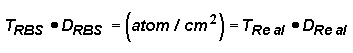
It is useful to note that where TRBS is the thickness obtained by RBS, and DRBS is the density assumed when calculating the RBS thickness, TReal and DReal are the actual film thickness and density, and atoms/cm2 is the two-dimensional concentration of atoms in the film (the concentration which can be accurately calculated from the RBS results without making any assumptions). Another useful feature of RBS is that since RBS will provide an accurate concentration of the total atoms/cm which are present in a film, if the actual thickness of the film can be measured by another method, then the density of the film can be calculated.
Related Techniques
By adding accessories to the sample chamber, or by changing the operating procedures, several other experiments can piggy back onto the RBS analysis. For example, measurement of the X-rays produced by ion bombardment is called particle induced X-ray emission (PIXE). Common RBS accessories include detectors for these X-rays, which are always produced, but not always measured. Hydrogen forward scattering (HFS) only requires the addition of a thin foil to separate forward scattered hydrogen from forward scattered primary He++ ions. Heavy ion backscattering spectrometry (HIBS) is the same as RBS, except that heavy ions are used instead of He++. Primary He++ ions with higher energies than the usual 2.2 MeV scatter, but the nuclear interactions become more complicated. In spite of these complications, called resonance effects, higher beam energies often prove useful. In some cases, the incident ions are captured by a target isotope and a different particle is promptly emitted. Measurement of the energies of these reemitted particles is called nuclear reaction analysis (NRA). Finally, charged particle activation analysis (CPAA) uses the accelerator to produce new radioactive nuclides which are measured with the same instruments used in neutron activation analysis.
Particle Induced X-Ray Emission
PIXE stands for Particle Induced X-Ray Emission. Several kinds of excitation beams produce X-rays with energies characteristic of the target elements. Thus, photon excitation (by X-rays) gives rise to X-ray fluorescence spectroscopy. Electron excitation in a scanning electron microscope or an electron microprobe provides energy dispersive or wavelength dispersive X-ray spectroscopy (depending on the X-ray detector). Charged particle beams of He++, or more commonly H+, afford PIXE spectroscopy. In all three cases, the excitation beam removes a core electron and X-rays are emitted with specific energies when outer shell electrons change state to inner shell. The X-ray energies are independent of the excitation process. The PIXE accessory is useful for heavy element identification on RBS instruments. These heavy elements have small differences in RBS energies, but distinct differences in PIXE spectra. Dedicated PIXE instruments usually use H+ rather than He++ because H+ provides higher sensitivity. If helium and hydrogen are mixed in the source, He++-based RBS and H+-based PIXE can be performed with the same accelerator.
PIXE has several advantages as an analytic technique. It offers signal levels similar to its electron beam counterparts, but better signal-to-background ratios. The background in electron spectroscopy arises from bremsstrahlung which is largely absent in PIXE because He++ or H+ ions, even at PIXE energies, have much lower velocities than electrons. Another advantage of PIXE over electron induced spectroscopy is that, like RBS, PIXE works with insulating samples. Finally, a proton beam can pass through a thin window and penetrate several centimeters through air. Because of this, unusual samples, such as valuable art work, need not be subjected to the rigors of a vacuum. PIXE finds applications in geology, archaeology, and art conservation.
Hydrogen Forward Scattering
HFS stands for Hydrogen Forward Scattering. An HFS experiment uses essentially the same apparatus as standard RBS. The analytical information obtained by HFS consists of hydrogen concentration versus depth. The sample is tilted so that the He++ beam strikes at a grazing angle. Helium is heavier than hydrogen, so there is no backscattering of He++ from hydrogen. Instead, hydrogen (H+ and Ho) is knocked forward with significant energy after being struck by He++.
The He++ also scatters toward the detector because of heavy elements in the sample. The number of He++ ions scattering at this low angle is large relative to forward scattered hydrogen. The He++ signal would swamp the H+ signal except that a thin foil (about 8 microns) positioned in front of the detector separates the interfering He++ from the H+. Carbon, mylar, and aluminum foils are commonly used. The foils cause significant energy loss and straggling in the forward scattered hydrogen. Although these effects limit the HFS depth profile resolution to about 50 nanometer, hydrogen (or deuterium) quantitation at surfaces is possible with 5 % accuracy down to 0.01 % detection limits.
Heavy Ion Backscattering Spectrometry
HIBS stands for Heavy Ion Backscattering Spectrometry. This technique uses ions heavier than He++. Collision cross sections are higher for heavy primary ions, and there are no resonance effects at available energies. These heavy ion beams provide advantages in trace heavy element determinations of light element samples. The matrix elements are all scattered forward and cannot contribute interference signals. The forward scattered analyte elements can also be useful for analysis. Measurement of analyte ions scattered forward by heavier primary ions is a general phenomenon called Elastic Recoil Detection (ERD). (HFS) is a special case of ERD.
The accelerators and detectors are the same for HIBS and RBS, but different ion sources are required. A typical heavy ion source uses a sputtering Cs+ beam impinging on a heavy element such as silicon from which negative ions (Si- in this example) are extracted. The charge stripper removes a variable number of electrons from Si-, leaving ions with mixed charge states and energies. The primary ion beam must be separated into components, usually in a magnetic field, before the beam strikes the sample.
Nuclear Reaction Analysis
NRA stands for Nuclear Reaction Analysis. Helium ions with less than 2.2 MeV energy undergo elastic recoil with all elements. Elastic recoil, like colliding billiard balls, can be described by classical mechanics. For ease of interpretation, most RBS analyses use less than 2.2 MeV He++ beams. Higher energy He++ ions collide non-elastically with analyte nuclei. This means that the collision cross sections can be much higher for certain (resonance) energies. At resonance energies, the analyte nucleus seems to absorb and reemit the He++ ion rather than simply scatter it. Quantum mechanics are required to explain these interactions.
An example is the well known resonance effect at 3.045 MeV for alpha particles scattered from 16O. The process is indistinguishable from elastic recoil except that the cross section is many times greater. Although variable cross sections resulting from higher beam energies complicate the analysis, the higher energies are useful in specific cases such as oxygen present as a single impurity in a thin layer.
At some resonance energies, the primary ion is absorbed by the analyte nucleus and a different particle (usually a proton, neutron, alpha particle, or gamma ray) is promptly emitted. Among the light elements, there are several potentially useful reactions such as 19F(p,alpha)16O. In this case a 19F nucleus absorbs a 1.25 MeV proton and promptly emits an 8.114 MeV alpha particle. Measurement of the alpha energy indicates the depth from which it arose. This is the nuclear reaction analysis technique.
Would you like to learn more about Rutherford Backscattering Spectrometry (RBS)?
Contact us today for your Rutherford Backscattering Spectrometry (RBS) needs. Please complete the form below to have an EAG expert contact you.