SEM-CL Webinar
In this webinar we will focus on SEM Cathodoluminescence (SEM-CL) Analyses for Materials such as compound semiconductors
Home » Microscopy Techniques in the Failure Analysis of Optoelectronics
Optoelectronic devices are playing an increasingly important role in the success of a wide variety of current consumer electronics and industrial applications. These semiconductor devices have been made reliable by careful design and technological advancement. Having carrier recombination rates thousands of times higher than other types of devices inevitably leads to degradation and ultimately failure that is often highly localized. To understand the root cause of failure, it is often very important to catch the problem as early as possible which is both a reliability testing as well as a characterization challenge as initiation sites can be as small as a few nanometers. EAG’s Microscopy group can help.
EAG takes an integrated multi-technique approach to best determine cause(s) of failure. Samples are first screened with non-destructive techniques for bulk characterization and defect isolation. Once a defect is isolated, highly localized destructive techniques are applied to take a deeper look to establish the root cause.


EAG divides FA characterization tasks into three levels. In each level, we employ optimal techniques for device characterization, defect localization, and ultimately root cause failure analysis. While we can supply all three levels of service, typically our clients perform level one characterizations themselves which identify candidates for level two and level three inspections that EAG carries out.
Level one: Non-destructive, routine characterization techniques are utilized first. This step should be done to every device. These techniques have the lowest spatial resolutions if any at all.
In this step, we typically employ electrical measurements (LIV), along with optical microscopy techniques such as bright/dark field imaging, etc. to identify defective devices.
Level two: Once a defective device is identified in level one, the sample will be brought into a second non-destructive failure localization step.
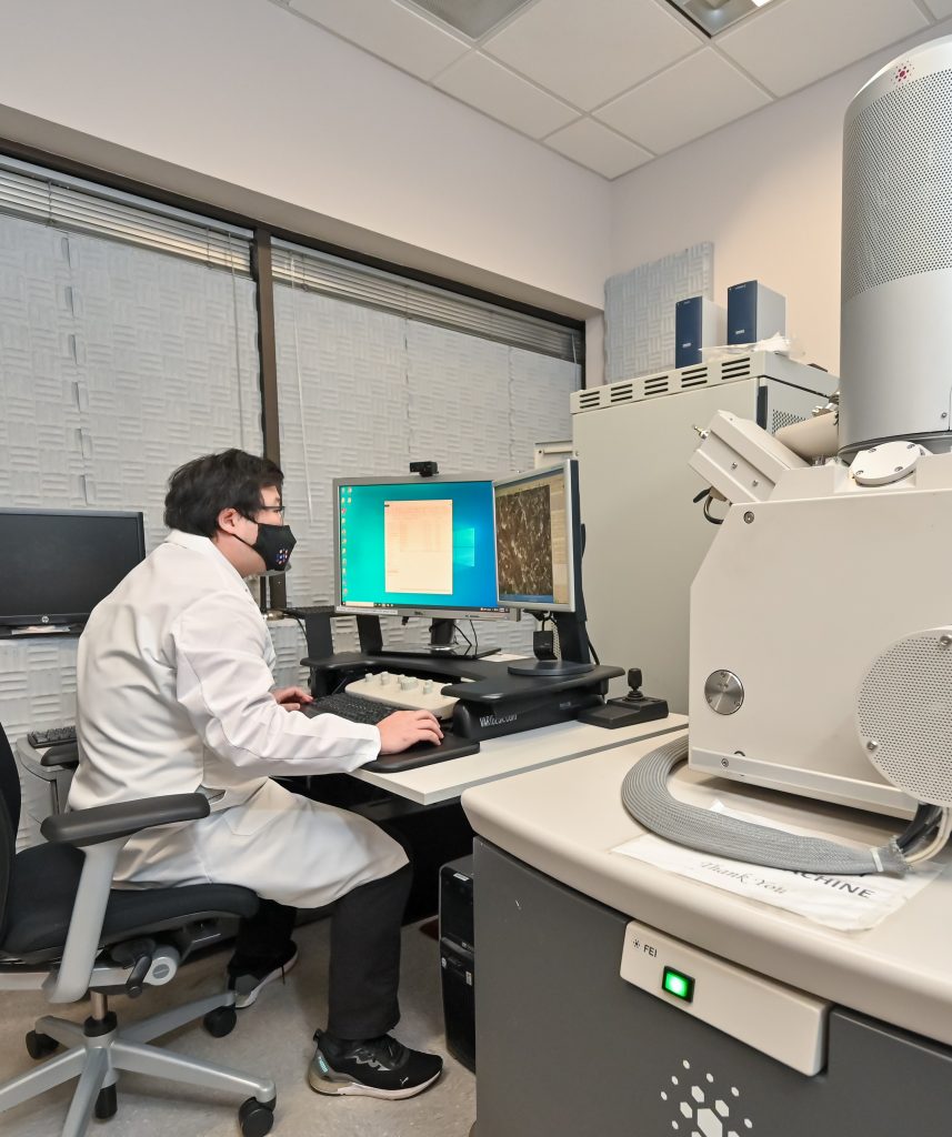
In this step, we can use optical techniques like Electroluminescence (EL), Optical Beam Induced Resistance Change (OBIRCH), and Emission microscopy (EMMI), or Scanning Electron Microscopy (SEM) based techniques like Electron Beam-Induced Current (EBIC) and Cathodoluminescence (SEM-CL) to further view and isolate the failure site with spatially resolved images.
Level three: If further, deeper understanding is required, we then perform destructive analysis on the sample to take a detailed look at the microscopic structure of the offending defect(s).
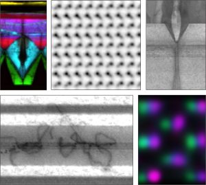
In this step, we typically utilize focused ion beam (FIB) and dual beam instruments (FIB-SEM) for sample preparation and cross-sectional analysis of a defect site. For yet deeper analysis, we employ Transmission Electron Microscopy (TEM) or Scanning Transmission Electron Microscopy (STEM) with EDS or Electron Energy Loss Spectroscopy (EELS) to investigate crystal defects and local composition/chemistry changes.
This deep FA process results in direct evidence for the how and why a device has failed.

In this webinar we will focus on SEM Cathodoluminescence (SEM-CL) Analyses for Materials such as compound semiconductors

Solids fall under two main categories: amorphous and crystalline. These two types of solids have different properties that may be more beneficial for certain products or applications.

In this webinar, we will explore the variety of microscopy techniques available at Eurofins EAG commonly utilized to characterize compound semiconductor materials.

In this webinar we introduce Deformulation of Pharmaceutical RLDs and understanding the Q1/Q2 Sameness Requirements for Complex Generics
To enable certain features and improve your experience with us, this site stores cookies on your computer. Please click Continue to provide your authorization and permanently remove this message.
To find out more, please see our privacy policy.